How does it work?
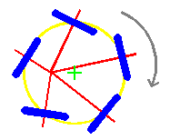
 | The adjacent diagram is a plan view (view from above) of 5 wheels, shown in blue, driven together in the direction of the grey arrow, steered by axles which are red. All 5 wheels are attached to a single rotor which rotates about an axis normal to the plane on which the wheels run, and this axis is represented by the centre of the green cross. Each wheel is individually steered about its own vertical axis (normal to the plane), and this axis passes through the centre of the contact area of the wheel and the surface below (similar to a castor, except that there is no offset distance of the vertical steering axis). All the wheels are steered such that the lines of their axles meet at a single point. In the instance shown, where the centre of steering is coincident with the centre of rotation of the rotor, the whole assembly does not move along the plane. The wheels move along the path of the yellow circle. |
Clearly, the laws of action and reaction dictate that there must be either at least two of these devices under a single motion platform or vehicle (to react against one another), or there must be a set of trailing wheels to prevent the whole vehicle from rotating, or the rotor drive must be referenced to a stationary point.
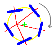
 | If the centre of steering is now moved away from the centre of rotation of the rotor, then we get the situation as shown in these two diagrams. The second diagram is a snapshot of the arrangement taken a short while after the first. The rotation of the rotor is now accompanied by a horizontal translation of the entire system, in this instance: down the page. Note that the distance between the centre of steering and the wheels is continually changing. |
 | In practice, steering is not usually achieved by variable length rods, as the diagrams imply, but by another method not described here. This method is depicted for clarity of explanation. |
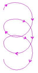
 | The path of a single wheel in the situation above is as per the purple line opposite. It is particularly important to understand that, under no load conditions, there is no scuffing or skidding of the wheels. Motion is achieved purely by steering and the reaction of one wheel against another as the system runs along the surface. |
In practice, the ratio of this steering offset distance to the radius of the wheel circle (in yellow) cannot usually exceed 0.75.
This concept is available for joint venture development and/or manufacture under licence, or outright sale.


